The original wheel is made from two steel pressings of two different diameters with 10 spokes which are joined by turning over the outer onto the inner to form a seam.
The centre holes in my samples are:
Inner - Ø 5/16"
Outer - Ø 1/4"
My special, part threaded shouldered bosses are made to the sketch below.
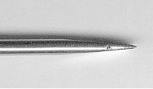
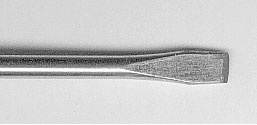
To convert the standard wheel into 20 spoke Driving/Coupled Locomotive wheels the pressings must be parted by prising up the turned over joint around the tyre section on the outer with a modified 4" x 3/16" wide slotted screw driver with the point sharpened to a chisel edge as shown, and lifting the inner from the outer by laying the wheel at 45º with the screwdriver pointing away from you for safety !
It is suggested that these operations are
carried out as required for a set of six wheels.
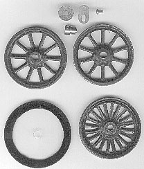 |
Referring to the illustration:
Top - Both parts must be ‘dressed’ to true shape on any suitable mandrel for each size. See sketch (Outer Ø 2.975") (Inner Ø 2.930"). After this operation the inner is reversed and replaced into the outer to produce the 20 spoke wheel as shown in the illustration , lower right. I recommend using any suitable retaining grade engineering or epoxy adhesive to secure the wheel parts to each other and then to the boss, but this is optional. The flange, lower left, is made from a 2mm thick high Impact Polystyrene Disc 3.25" Diameter with a Ø3/8" centre hole and a black rim 3/8" wide marked with a permanent marker. The part threaded shouldered boss is 1/2 " dia brass made to the drawing. The eccentrics are self explanatory as they are standard Meccano parts. |
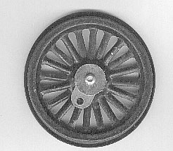
A finished wheel with boss and Meccano
eccentric fitted
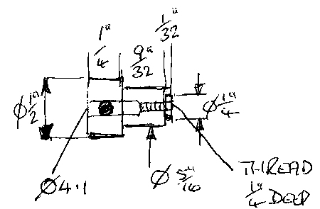
19A Loco Wheel Boss Drawing
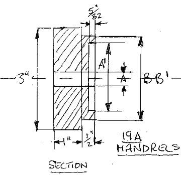
A Ø 3/8" clearance for boss, and
A1 Ø 2.650" are common to both mandrels.
The 3" diameter x 1/2" and 1" lengths
are minimum dimensions for material size and length for work holding
For inner part Ø B = 2.925"
For outer part Ø B = 2.975"
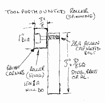
Truing & Dressing parts - Use a toolpost mounted roller tool - See sketch below, applying pressure with the cross slide until true and round but do not go too far or the component will be difficult to remove from the mandrel.
Note: A 3" dia pressure disc x minimum length 1/2" should be made and this should have a no.3 Centre drilled hole. Hard pressure should be applied to the pad by a dead or live centre in the tailstock until while work is in progress. This will be used for 19B pulley "Boxpok" style flanged wheel and solid flywheel conversion modifications, about which, another DIY article will soon be published.
Note: 1 off Required