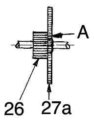
Figure 1 19/57T
This prevents the gear from turning
Both types can be made with a pinion face width of 6mm or 4mm.
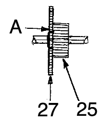
Figure 2 25/50T
The main reason for modifying gears and pinions is that Meccano gears and combinations occupy too much linear space due to the bosses. A valid second is excessive face width. Both factors impose unnecessary restrictions on what can be built especially to smaller scales.
There is no reason why Meccano gearing should not follow common engineering practice. For example double gears are not new. The No1 clockwork motor provides some.
‘Double gears’ using any combination are feasible, although I accept 1/2" or 1" pitch is the most desirable. Modified gearing and associated parts become dedicated equipment so they should ideally be made in pairs or fours and recorded in Meccano stock lists as modified parts.
The first ‘double gear’ combinations I made, shown below, were based on the most common gears as they are readily available second hand.
The same size Plastic gears can be altered
similarly.
|
Figure 1 19/57T |
This prevents the gear from turning
Both types can be made with a pinion face width of 6mm or 4mm. |
Figure 2 25/50T |
The following modifications greatly increase potential use when linear space is restricted and have no detrimental effect on performance in normal use. Fig 1 shows a sectional drawing Left, as a view on the Centre Line in direction of arrow A detailing a full set of modifications which can be carried out on all PINIONS as listed. Plastic 19T pinions and all Brass 19T and 25T pinions. Note: All 15T and 11T pinions can be grooved and slotted only.
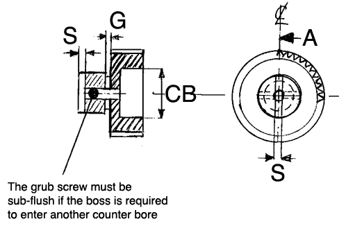
Figure 3
Key:
CB - Counter bore Flat Bottom drilled
Ø 3/8"clearance x 1/8" deep for closer gear cluster potential.
G - Gap Machined 1/16" wide to Ø
7/32" (0.218") for selector strip as shown in Fig 4
S - Slot - Cut by hand and filed or machined
in boss face for use with a male dog clutch, Part No 144a.

Figure 4
They are designed to operate across the face of 50T Contrate gears with a central neutral position.
Note: If used on 25T Contrate gearing they should have the face width reduced to 1/8" to provide sufficient clearance and grub screws in both situations must be sub-flush to clear the Contrate gear boss.
Referring to the drawing, Fig 5, the gap G is formed naturally but may have to be widened for thicker gauge strips. This is done by machining the back face of the right hand pinion until a 1/16" wide gap is achieved for the selector.
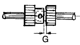
Figure 5
All cluster gears shown can be used on
either Tri axles as shown or on keyway rods. Grub screws and key
bolts should be super glued or fixed with engineering adhesive to ensure
free sliding fits and if key bolts are used on reversing pinions the heads
should be filed off to clear the central boss in the Contrate gear, as
reversing pinions are dedicated for special use!
The drawing below is based on an original by Phillip Webb in the HTMC Newsletter Autumn 2000. I developed the 11T Zinc Double pinion conversions for compact reversing gears and used them on ‘Aggravator’, my Micro Block setter crane.
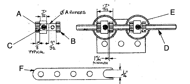
Figure 6 -- 11T REVERSING PINION
For use with 25T Contrate gears
A - Left hand pinion - Ø A 7/32"
(0.218") Drilled x 7/32" Deep as shown.
B - Right hand pinion Ø A x 9/32"
long as shown (0.28") turned to produce a light press fit in A
C - Grub Screw. This must be Loctited
or super glued in position and sub-flush in the pinion boss. The assembly
must be a free sliding fit on the tri-axle D and the boss must clear the
centre of the 25T Contrate gear E.
The overall dimension of the double pinion
assembly must not exceed 17/32" (0.531") to satisfactorily provide a central
neutral position as shown on the Right hand side of the drawing and the
operating gap for the selector F must not be less than 1mm (0.040")
F - Selector .The selector shown is based
on a 5 hole narrow strip but it can be made to suit requirements and is
not supplied with reversing pinions.
Fig 7 Below, shows a 19T /25T pinion double gear combination but 15T/19T or 15T/25T combinations can also be made using the same technique described previously. The pinions are shown in standard form but can be counter bored on the faces if desired. They should not have grooves machined in the boss.
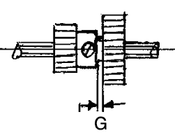
Figure 7
The gap, G, is achieved by the same
method described previously.
A - No31 - 38T gear. The face is reduced to 5mm from the boss side to allow the groove to be machined in the boss with sufficient clearance from the
screw holes. The gear is then bored through 1/4" Dia.
B - The Pinion can be 25T x 1/4" face or 25A, 19T 26, or 26A, or a 15T x 1/4" face 26B. These are machined to a light press fit with the bore of the No31 gear so that the screw holes are in line when fitted.
C - Counterbore - Ø 3/8" Clearance for boss when used in close proximity..
G - Gaps 1/16" Wide to Ø 5/16" Note: After machining the groove to the correct diameter the pinion should finish with 5mm face width approximately.
Note: Selector should be made similar
to Fig 4 but from a standard strip with the open slot 5/16" wide.
The drawing shows a slot in the boss but this optional as it can be machined or cut and filed by hand when needed.
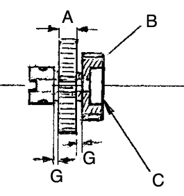
Figure 8
SOME SOLUTIONS
1. Standard 25T brass gears can be faced
off to a 2mm face width (0.08") and these are slightly better for compact
reduction gearing.
2. If a 13T pinion is used with a Zinc
25T they mesh at 1/2"pitch which is a far more satisfactory all Meccano
solution.
3. 11T and 25T Zinc gears can be meshed
by using the standard threaded pin as a lay shaft, taking advantage of
the undercut beneath the integral nut to reduce the pitch to 12mm and locked
in place. There is sufficient play in Meccano holes in plates and
bush wheels to do this. I have also made 1.125" long special threaded
pins from 1/4" A/F Brass for more than one double gear and greater reduction.
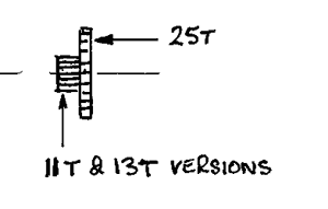
Figure 9 - 11/25T & 13/25T double gears
13/25T double gears work at standard pitch.
Face width of the pinion section is 4mm
(0.157") approximately.