Free-lance Non-release Horizontal Cross Compound Steam Engine by Mike Dennis
Designed and Built By Mike Dennis June/July 2002
Member - H.T.M.C.,R.M.G.
Approximate scale 1/10
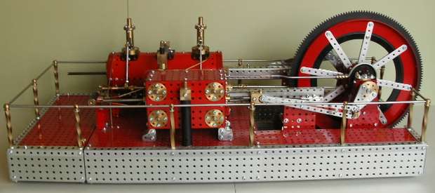
Introduction
This engine is similar to some small industrial Compound engines and was built to demonstrate the use of drop valves on the L.P. and Corliss valves on the H.P. cylinders. The drop valve layshaft on the L.P. cylinder is utilized to drive an oil feed pump for valve lubrication to both cylinders which would have been fairly common practice. The steam valves (Inlet) are placed at the top and the exhaust valves, below, on both cylinders. Engines such as this were built for medium to low constant speed running (50 - 100 RPM) and some had no trip gear (hence the term non-release).
A governor was also optional as steam pressure and ingress could be controlled manually via a gate valve which therefore had a governing effect. The piston rods are extended by 'Tail rods' to minimize wear on the bore and glands and covers would have been fitted for safety as they are on the model.
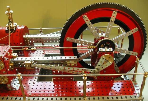
The toothed flywheel would have allowed geared, high speed, over-head counter shafts enabling machinery to run often for 24 hours daily over a 6 day week. Maintenance work was carried out on the seventh! I normally run the model at about 40 - 60 RPM to allow viewing of the valve gear operation which is 'timed' as near correct to 'live-steam' conditions as I can ascertain.
Compounding
The main reasons for compounding were the advantages of overall efficiency and less space than was required to operate a beam engine of similar cylinder capacity. A small compound would take up less space and produce more power at less steam pressure on the LP cylinder from a relatively smaller boiler.
Valve Systems - Drop Valves - LP (Large Cylinder)
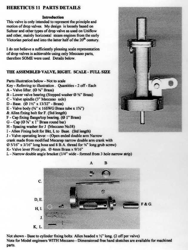
The drop valve design used on this engine is similar to a piston valve. It is loosely based on the types featured on Sultzer Brothers and Lentz engines. They are also driven by spur and bevel gearing at 1:1 from the crankshaft via operating rods fitted to eccentrics on a layshaft. Drop valves were in common use mainly on horizontal engines from the early Victorian period. Later, they were fitted on Uniflow and other engines in constant productive use in the latter half of the 20th century, some as late as 1970 in the USA.
Corliss Valves - HP (Small Cylinder)
Corliss valves are semi rotary valves controlled from a wrist plate (center from the cylinder) via an eccentric. Invented and patented by the American engineer, George H. Corliss in the 1840's; engines fitted with Corliss valves were, like drop valves, also renowned for efficiency and fuel economy. They were more widely used except for the simpler and less expensive slide valve.
The model
Overview
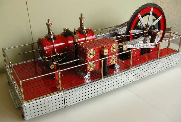
Hereticus II is the second engine in a series of models of my own design which are built WITH Meccano. It is International in that Geoff Wright's (MW models), Jackarno, David Fellows, Ashok Banerjee and Mecarep special parts are used. Meccano parts were supplied by Dave Taylor.
Overview
Mecarep parts and systems feature Meccano compatibles for various sizes of shaft and four other rod sizes are used on the model apart from standard axles. The crankshaft and all it's associated parts are Ø 3/8" Silver steel. The Corliss valve gear uses parts from the Mecarep Micro rod system and special Narrow cranks with narrow bosses and 8 B.A. thread grub screws. (Ø 3/32")
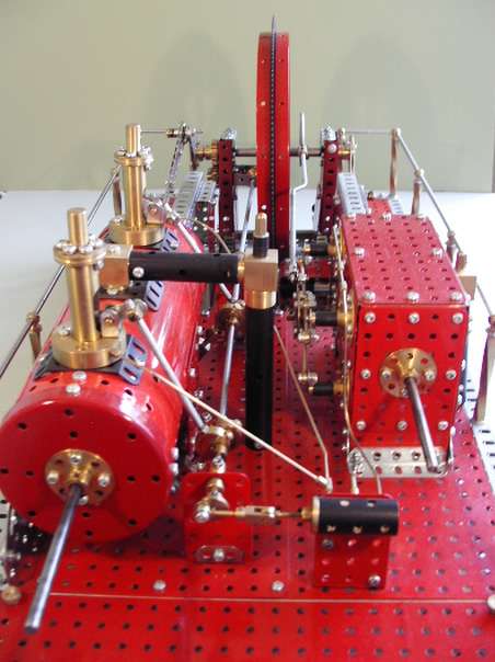
Axial view
The piston rods feature Mecarep system 236(6mm) parts and other specials. The librication system pipe work is Ø1/16" Brass with Ø5/32" and A/F Hexagonal Brass fittings. The 'tail rod' covers and steam pipes are MW sleeve pieces secured by special parts designed for the model. The layshaft and drop valve rods on the L.P. cylinder and the main eccentric rod on the H.P. cylinder are Meccano, proving that some was actually used.
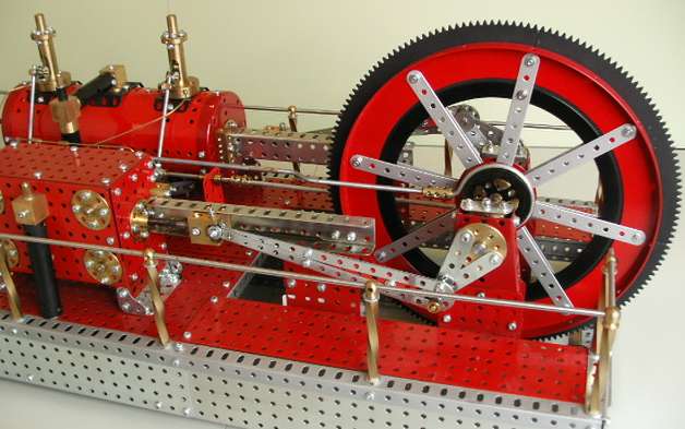
Rear half
Back end
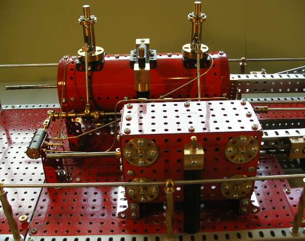
Front end
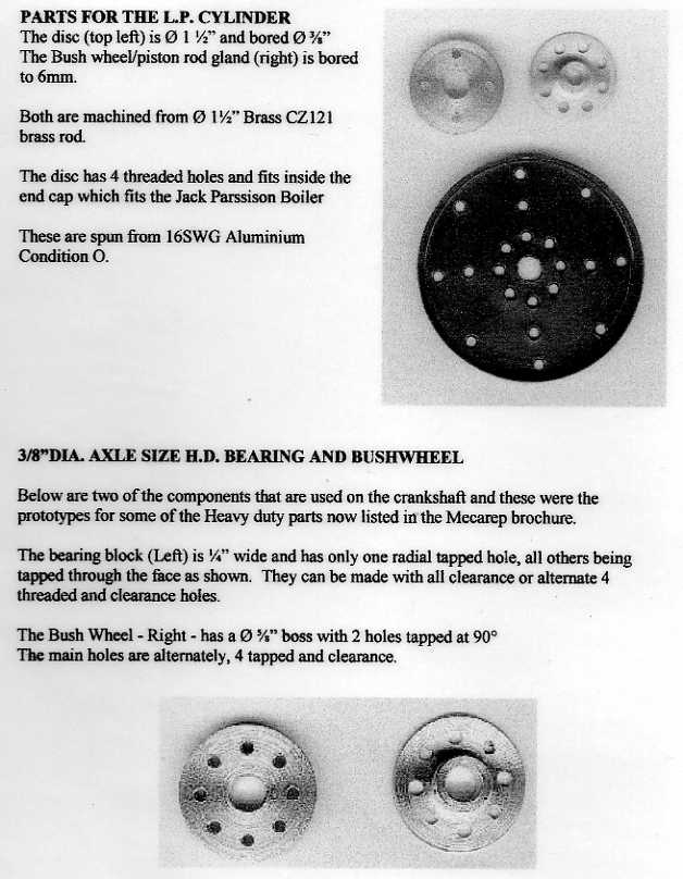
The L.P. Cylinder is a 9 1/2" long x Ø3 1/2" "JACKARNO" boilder - (Jack Parisson) made in Australia! The end caps are spun aluminium S1C (condition 0) of my own design which fit OVER the boiler and are fitted with 6mm (System 236) bush wheels and special threaded wheel discs to eliminate the nuts. The 1/4" square barley twist handrail stanchions and corner Ball fittings are also my own design. The handrails are 8 SWG radio control wire from a model shop which is Meccano size which can be 'polished' in the lathe after cutting to required length.
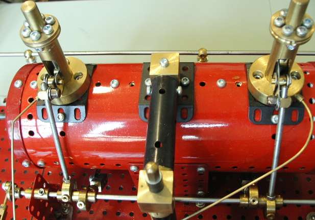
Drop valves
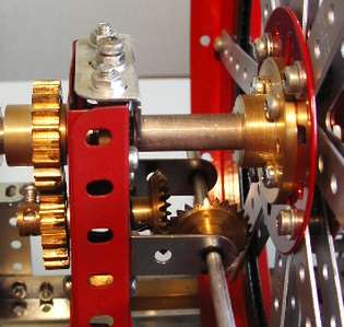
Drop valve drive
The pinion driving the quadrants on the flywheel is a 16DPx36T screw cutting gear change wheel from my Raglan lathe. Any set of 16DP hange wheels from old scrapped back geared screw-cutting lathes such as Myfords, Boxfords or South Bends provide a source of several alternative gears rather than only quadrants and the 16T pinion in the Meccano system. A boss can be made to reduce the hole in the gears to suit Meccano or any HD axle system. Change wheels are available at s/h dealers.
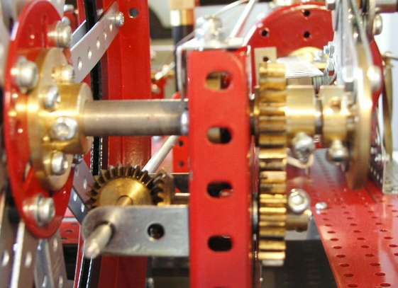
Drop valve drive
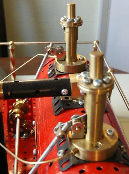
Drop valves and eccentrics
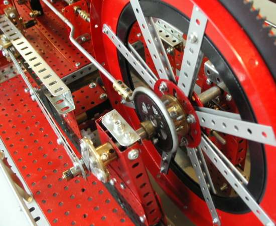
Eccentric
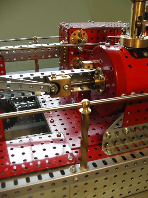
Drop valve cross head
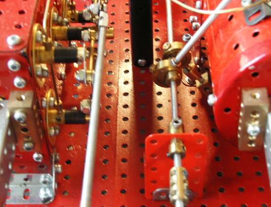
Valve gear
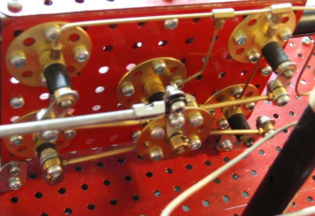
Valve gear
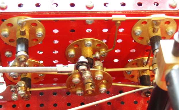
Valves
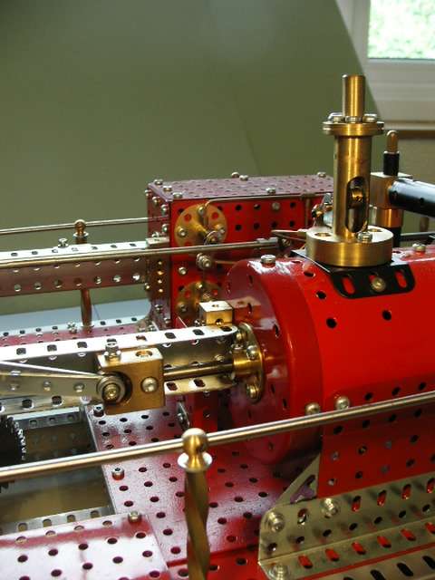
Drop valve and cross head
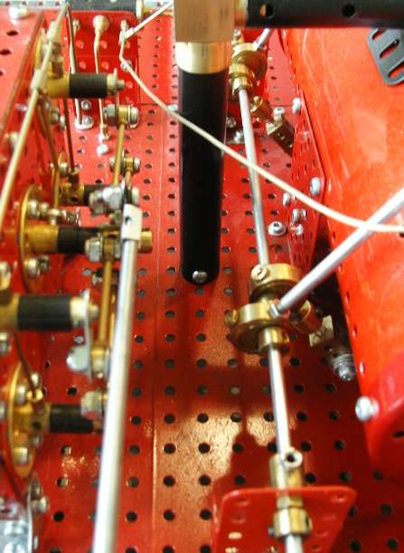
View through
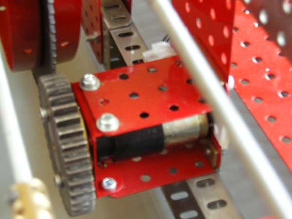
Motor and 36T drive gear
The motor is a Faulhaber 2230 V6 12S type as supplied by Geoff Wright (MW Models) with a 4mm shaft which runs at about 130RPM on 12 Volts driving flywheel mounted Meccano quadrants via a 36T 16DP gear. The main frame is made from a mixture of Meccano angle girders, David Fellows flat plates and 1 1/2" x 1/2" channel section plus a liberal use of Exacto Red flat plates.
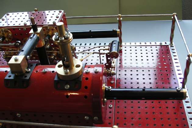
Front with covers
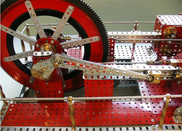
Rear view
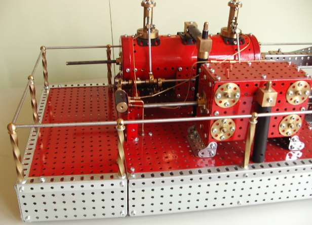
Front half
The HP cylinder is all Meccano which allows me to say 'Some Meccano was used'. For proof, see the quadrants, flywheel rim, spoke overlays and read the words on the HP cylinder top plate! The spoked flywheel contains another Jackarno part for the 167b which is in effect an 8 spoke 'Spider' - very useful as it makes for accurate construction and a 'true running' flywheel without resorting to a jig. He makes them in narrow strip form for both the smaller flanged rings too!
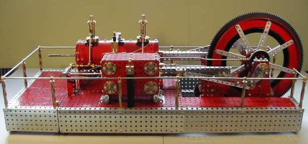
Overview
Special Parts
(c) Mike Dennis 2002