Designed and built by Mike Dennis August/September 1999, modified September 2005
Member - H.T.M.C., R.M.G.
Approximate scale 1/6
Originally placed at http://www.patbelford.com/toys/library/reynolds-engine/index.html (site no longer active)
Introduction
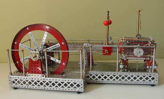
The main reason for making this particular model is to demonstrate Corliss valve operation which uses Mecarep Micro system parts involving the use of 8.B.A. threads 1/8" Wide collars and 3/32" diameter brass rods. Whenever the engine is displayed I am accused of using too much model engineering which tells me I have achieved the main objective of model engineering WITH Meccano! The system must be allowed continuous development just as in real life. The company is so arrogant that it has never in its history catered for enthusiasts or listened to model engineers who use it and their development record is appalling.
The model was built using the only references I have which are the two engravings shown in the reference material, some valve diagrams in the Joshua Rose book 'Modern steam engines' originally published in 1887 - Drawings 1 - 4 refer, and details of the Reynolds trip gear in the book 'Corliss, Man and engine, by William D Sawyer shown which is shown on here. The engine ran at around 100-120 RPM on about 60 PSI steam pressure which was fairly typical of all Corliss valved horizontal engines although they are known to have run efficiently at speeds of up to 160-180 RPM. The model runs more slowly to allow viewers to watch the wrist plate, valve, governor and dashpot control rod movements. I have not modeled fully working trip gear but the dash pots are timed and triggered by Meccano metal spring clips. Please note that the above notes and drawings are provided for the model maker to interpret the model to their choice. Model engineers will make their own decisions as to the methods and materials used.
This engine would have insulted the original and looked hideously out of proportion if only Meccano parts had been used, especially for the valve and governor control rods and other parts at this scale. I could certainly not have afforded to build it to a large enough scale to use all Meccano and it would probably not have fitted in my bungalow without causing 'world war three' with 'she who must be obeyed'!
There are no short narrow cranks, Ø 3/32" rods or narrow collars in the system and neither are there any parts I considered suitable for the connecting rod, cross head assembly and slides. I use Meccano parts and David Fellows or Ashok's alternatives wherever and whenever I think they are appropriate because Meccano have refused to develop certain parts which their systems provide but as my models are always described as made WITH Meccano and I never enter any competitions I do things MY WAY by the Frank Sinatra method.
The model was included in the ISSES (International Stationary Steam Engine Society) bulletin Vol. 21 No 4 which is an achievement because the society usually publishes only historical articles and live steam matters.
Edwin Reynolds
Edwin Reynolds was the virtual successor to George H. Corliss in steam engine design. His trip gear was the most popular in use after 1890 and the company he joined in 1877, E.P. Allis and its successor, the Allis Chalmers Company had built over 6000 engines by 1914. Reynolds was born into a large farming family in Mansfield, Connecticut, U.S.A. on March 23rd 1831. After leaving school at 16 he served a 3 year apprenticeship in a small country machine shop where he learned to use 'initiative' as the equipment and tools were not very good! Around 1850 he joined the Woodruff and Beech ironworks in Hartford , Connecticut, until 1857 when he moved to the Mid West to join Stedman and Co, in Aurora, Indiana, where he was eventually appointed superintendent. He left and joined Corliss in 1867 as a salesman and engineer becoming general manager in 1871 but his talent was stifled by George Corliss, who still controlled design. In 1877 he left to join E.P. Allis and Co, in Milwaukee, Wisconsin, who were a struggling small company employing 150 people. He received less salary but had a free rein for his talents, and saw the wider market potential for steam engines in the Mid West due to greater concentration of business and a growing number of industries.
Reynolds Corliss
The first Reynolds engine was a single cylinder horizontal engine with 14" bore x 36" stroke and was built in 1878. By 1895 E.P.Allis had built 500 and by 1897 the figure was well over 3000. These engines were equipped with Reynolds patented trip gear, which, with its compactness, simplicity, and suitability became the most popular type of trip gear used on Corliss engines. Other advantages were that its parts all hung on the valve stems and bonnets. It was safer regarding 'runaways' (tendency of the valves to go out of phase) and ran more efficiently and quietly at higher speeds than earlier designs.
Design and construction notes
Overview
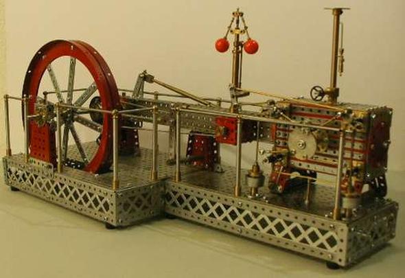
The model has a total of 750 parts which includes Meccano hexagonal nuts and Allen bolts almost throughout. 618 parts are Meccano including modified parts and 117 are not. Despite this figure which includes 15 non Meccano nuts and screws the model still meets my intended 70-80% Meccano parts criteria, for scale models made WITH Meccano.
Overview
I noted some common factors in other articles on Corliss horizontal engines and was able to estimate the Flywheel, bore and stroke dimensions to approximately 1/6 scale - The Flywheel would have been theoretically larger but as this engine was built to suit Meccano parts a compromise had to be made so it is approximately 5' dia with a bore of 13-14" and a stroke of 27-28" which I subsequently discovered was reasonably close for a small sized Reynolds engine of the period. The model is finished in standard Mid Red Meccano parts where used. Painted parts are Monza Red and Pulsar Silver from the Rover range of Halfords Car paints after application of 2 coats of Halfords Grey primer. Other parts are BZP finish. (Bright Zinc plate) and natural brass.
Rear view
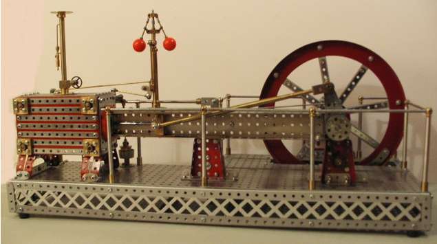
The flywheel on this engine has 8 spokes which conveniently allowed the use of two 167b large flanged rings to be used for the rim! The boss is made from two 8 hole Mecarep heavy duty (9/16"dia) boss parts. The spokes are four 19 hole strips sandwiched between the flanges and these are cladded with 16 6 hole narrow strips to give them a better appearance and add bulk. The governor drive pulley is a converted 2" pulley modified to suit the 5/16" dia. silver steel crank shaft, while the valve eccentric is a specially made block and slip ring type which gives 5/8" travel to a purpose made Aluminium wrist plate assembly mounted on the cylinder side plate from which all the valve gear is driven by connecting rods and linkages.
Valve gear
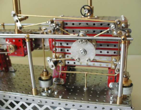
The only valve gear parts not functioning correctly are the Reynolds trip catches on the inlet valve bell cranks which are made from metal spring clips but they are timed to coincide with the dashpot movement as nearly as I can estimate how the prototype would have been set up.
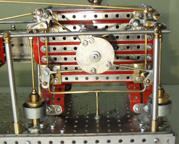
Valve gear
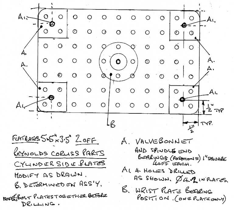
The cylinder was the major deciding factor for size in this case rather than the flywheel which is more usual. The Sides are two 5 ½" x 3 ½" and the ends are two 3 ½" x 2 ½" flat plates. A No 52 5 ½" x 2 ½" flanged plate forms the top. The cylinder is cladded with 19 x 11 hole narrow strips and the front plate is embellished with a conical disc mounted on a no boss face plate. The opposite end has a wheel flange with extra holes drilled to mount it on the end plate and secure the offset main frame which is made from two 1 ½" x ½" David Fellows channel girders
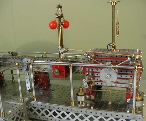
Valve gear and governer
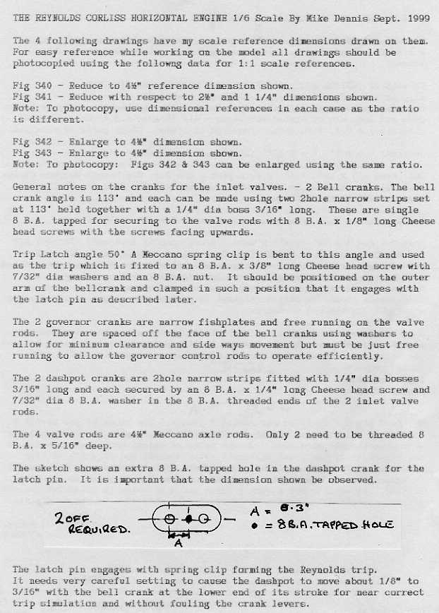
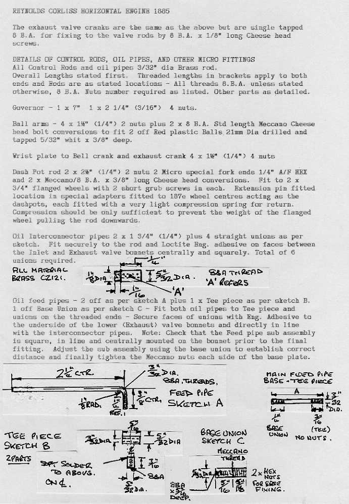
All the valve gear, dashpot rods, governor linkages and oil feed pipes to the valve bonnets are Mecarep Micro system (3/32" dia and 8 B.A.) parts, and the trip lever and governor cranks are 2 & 3 hole narrow strips fitted with special narrow bosses, some of which have 8 B.A. tapped holes for grub screws where needed.
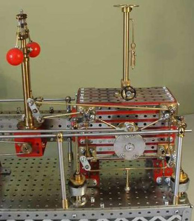
Valve gear and governor
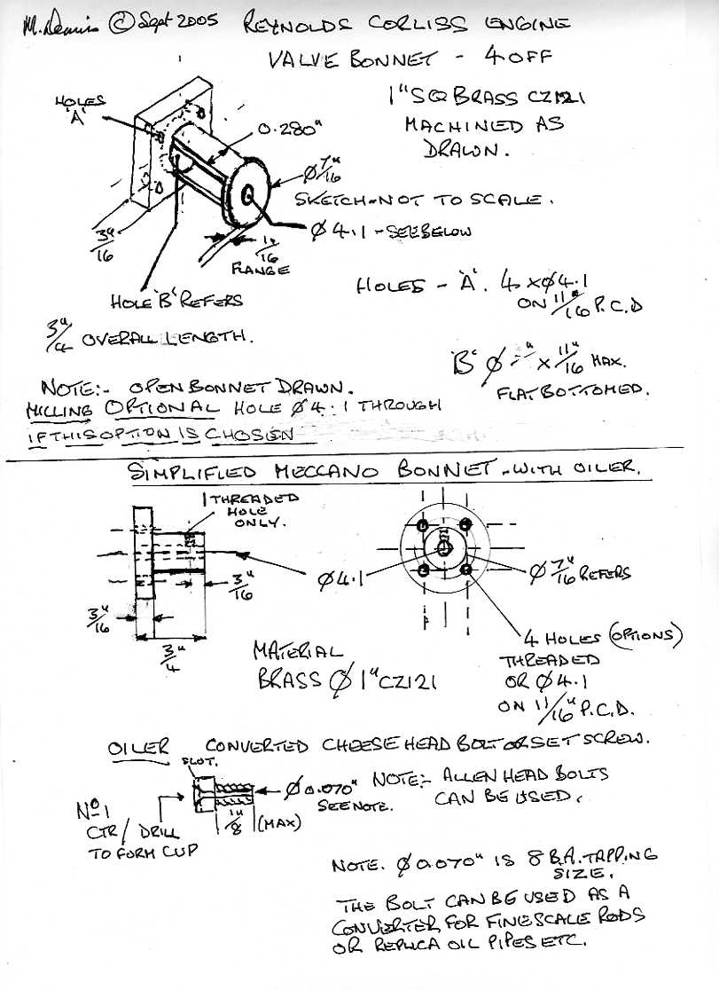
The valve bonnets are made with 1" square brass ends and ½" K & S tube milled out exposing the valve rods as in the real engine. This cannot be achieved with any Meccano parts. The valve rod end bearing blocks are 1" square. All parts made for this engine can be repeated.
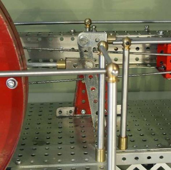
Eccentric rocking gear
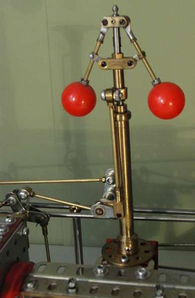
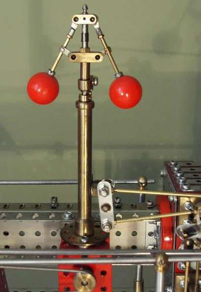
Watts governor
The working
governor is a Watts type driven from the crankshaft pulley
via a large band to a ½" pulley on the governor gearbox.
On this shaft a 25Tcontrate gear meshes with an 11T pinion
on the governor shaft. All the linkages and arms are
purpose made and the balls are ex-Cromptons Diggers Prize
amusement machine parts. The crank shaft is chain driven
by a Faulhaber 12Volt motor mounted on the inside of the
main bearing. The drive sprocket is a 14T Meccano sprocket
which drives an 18T with a heavy duty boss on the
crankshaft.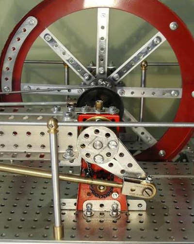
RC crank and drive
The Flywheel and cylinder block are all Meccano except for the valve bonnets and blocks which are machined items as nothing even closely resembles them in Meccano. All the valve and governor rods, linkages and collars are specially made for the engine. They are Ø 3/32" with 8 B.A. fixings for which I make no excuse and some are based on Mecarep Micro system parts.
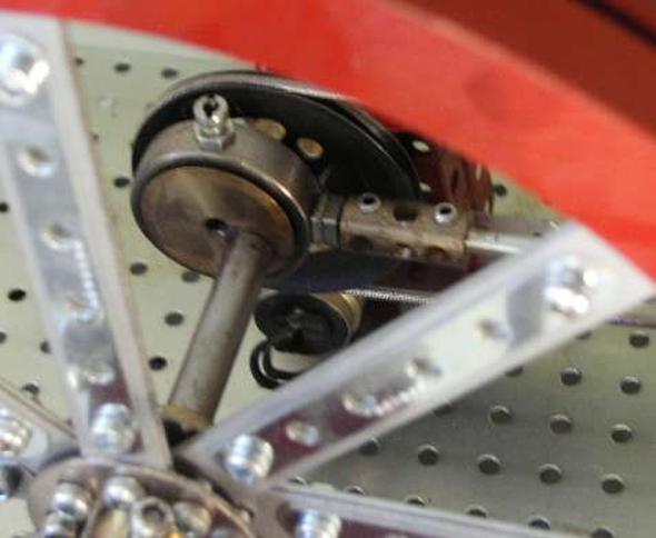
Eccentric
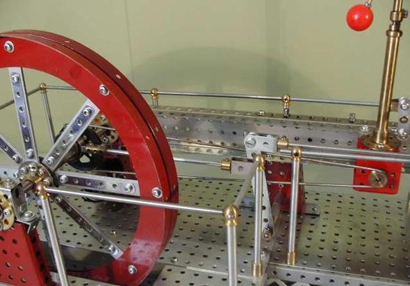
Eccentric
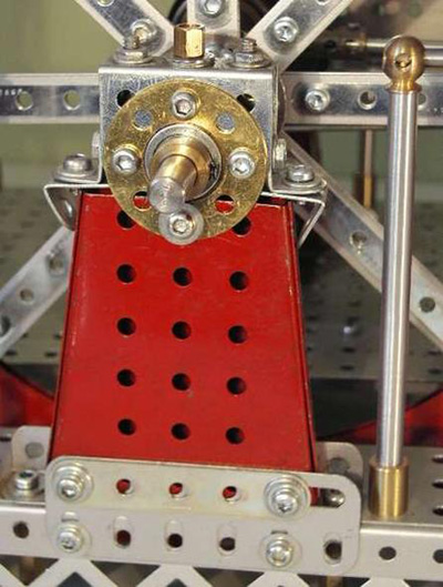
Main bearing
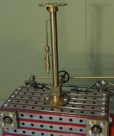
Steam pipe and manometer
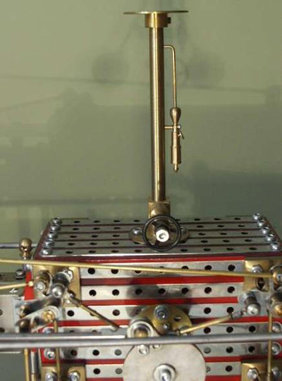
Steam inlet valve and manometer
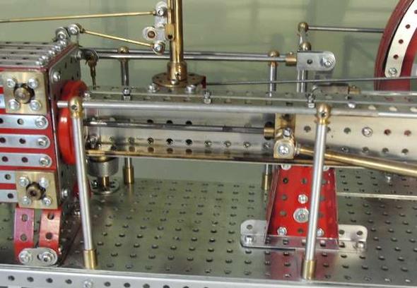
Cross-head, slide and cylinder back end
The handrails are ؼ" Brass with Meccano handrail couplings at the top and special adapters at the bottoms of the stanchions secure them to the base, which is a Meccano girder construction using old braced girders to enclose it and David Fellows flat plates to provide the top.
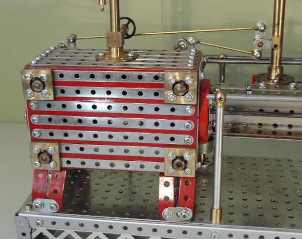
Cylinder, opposite side
Reference Material
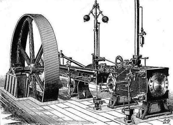
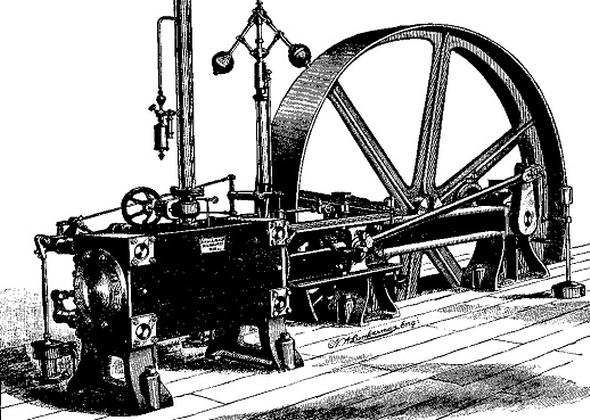
Reynolds Engine Engraving
This Engraving shows the engine viewed from the valve gear and Flywheel side. It can be compared with the model which is made to approximately 1/6 scale.
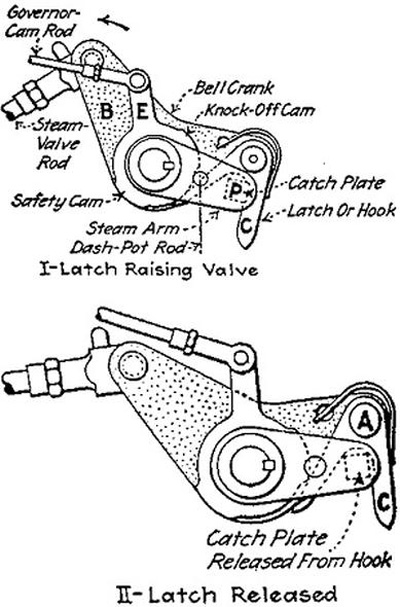
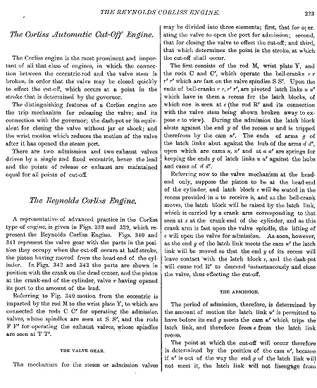
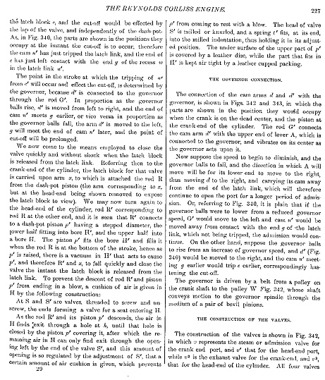
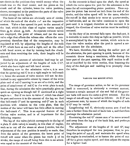
Reynolds trip gear
Drawing not to scale
The valve latches
on the model are represented by metal spring clips
positioned so as to operate the dashpot rods as near to
the prototype as possible.Engines with Corliss valves showed valuable savings in fuel costs over those using slide valves and this was a major contributory factor to their popularity. Edwin Reynolds held 52 patents and played a very important part in the formation of Allis Chalmers Co., in 1901, then due to poor health he retired in 1905 and died in 1909.
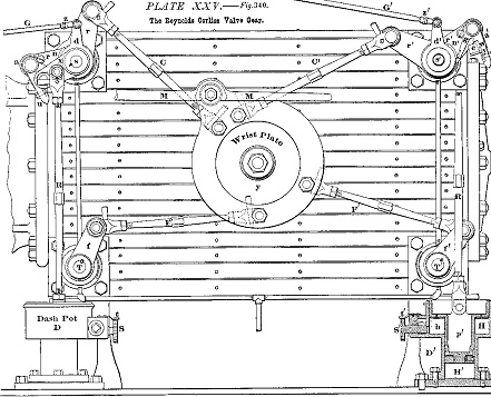
Reynolds diagram No 1.
Drawings are 1:1 scale assuming 5.5 x 3.5" flat plates are use for the sides and 4.5 x 2.5" for the ends. - This drawing shows the basic layout of the wrist plate, bell cranks, valve and governor linkages. The 2 inlet valves are at the top and the exhausts are at the bottom.
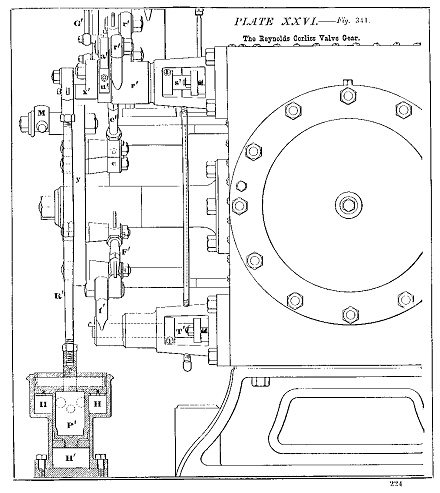
Reynolds diagram No 2.
End elevation showing construction of the cylinder, the valve bonnets and relative positions of the valve operating levers, inlet valve bell cranks, the governor levers and dashpots with their levers and rods.
1" square valve blocks and machined bonnets are used on the model.
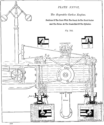
Reynolds diagram No 3.
Scale ½ full size
Scale ½ full size
This drawing should ideally be enlarged to full size and used as the datum to set up the engine when completed noting the angle of the wrist pin in relationship with the positions of crank and piston and crank as stated. Note also the attitudes of the inlet valve bell cranks and all other levers. If scaled up as described it can be the main reference to produce the governor parts, piston rod guides, and several other details.
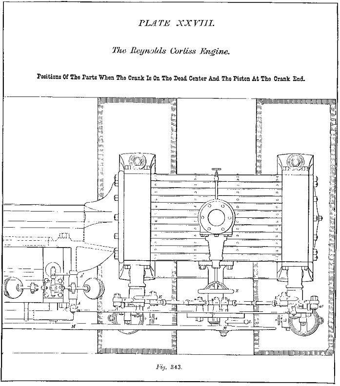
Reynolds diagram No 4.
Full size
Full size
The drawing can be used for further details to make parts in conjunction with Nos 1,2 and if enlarged, No 3
Reference text
Reynolds Engine Engraving
This Engraving shows the engine from the crank side.
Construction Notes
(c) Mike Dennis 1999