
 |
| INTRO | PARTS |
SETS Moubal Jumbo |
MANUALS Moubal Jumbo |
MARKETING |
PRICE
LISTS |
BUILDING |
MOUBAL RELATED |
BUILDING A MOBACO MODEL |
||||||
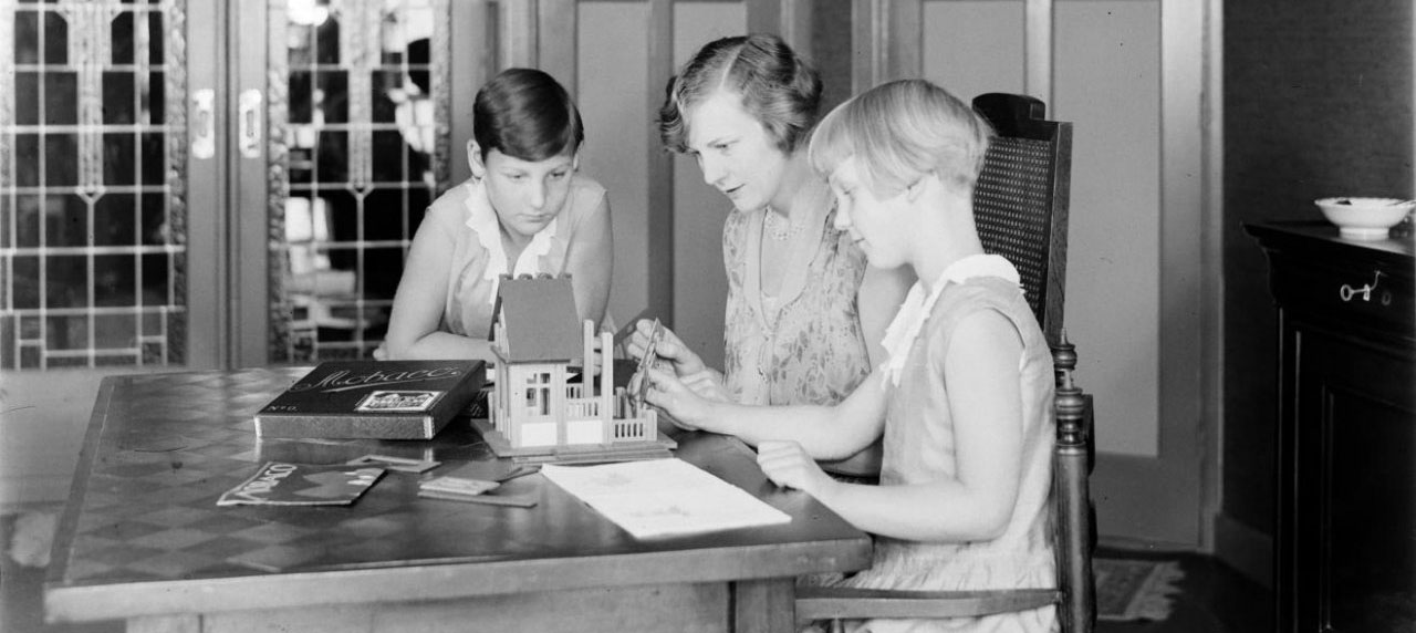 Image courtesy
Nationaal Archief.
1931 photograph by Willem van de Poll of his wife Nell Langlais and her daughters Hans (left) and Renée playing with Mobaco (cropped). Note: Shown is a 1931 Set 0 with
square windows and the new box
design with a cursive logo. A price list
with a Job de Nijs illustration lies folded on the
table.
A gnomes 00-0-1 Manual lies on the table, recognizable by the larger perspectives than used in the earlier instruction manuals. The manual is opened to designs 5 and 6, and design 6 is being built. This shows that in 1931, the gnomes manuals were in use. Hardly visible behind the house lies the small instruction leaflet. In a Natuur & Techniek article, also from 1931, we see this set being packed with Art Deco manuals (and the instruction leaflets). So in 1931, they produced sets with the Art Deco manual and sets with the gnomes manual. The Art Deco manuals were probably leftover stock. This indicates that the gnomes manuals were introduced in 1931, the same year the gnomes brochure is mentioned in a trade fair article. |
||||||
|
STEP BY STEP INSTRUCTIONS Construction of Model #48 is illustrated here. It's really easy!  The instructions are very efficient - the entire model is explained on just one page! The roman numerals of the floor Diagrams are keyed on the perspective. Step 1 - Getting Started  Diagram I shows which ground plate to use (the one with 4 x 8 holes). If you ever plan to move the model, set the ground plate on a tray or so. The columns tend to drop through the holes when you lift up the ground plate. 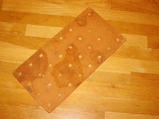 Step 2 - Setting the columns 
Diagram I also tells you which columns to put where: small numbers inside the squares indicate the length of the columns (2, 3 or 4).  Step 3 - Inserting wall panels 
Diagram I also tells you which wall panels to insert: use the part number indicated between the squares. Each cardboard items is imprinted with a part number, which makes it really easy. Sometimes you must stack two parts. First insert the bottom number (often part #22). 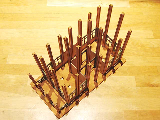 The columns are now pretty straight, although a little wiggly at the corners and in long walls. But that's taken care of in the next steps. Step 4 - Adding top plates and floor plates  To give the model rigidity, and to create floors, top plates and floor plates are inserted over the columns. Diagram II shows which plates go where. As you can see, the diagram is not quite to scale. In reality, the narrow strips aren't as wide.  Step 5 - Second layer of top plates and floor plates 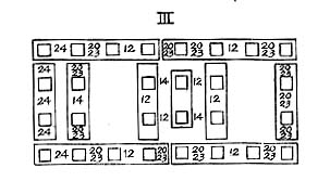 Diagram III shows which plates go where.  Why a second layer of top plates? As you can see in the photo, there are gaps between the top plates, which are weak points in the structure. Especially at the corners. Adding a second layer of plates that bridge over the gaps takes care of that. By the way, this system is the same as used in traditional wood frame construction: walls always have a double top plate, with the joints staggered for strength. 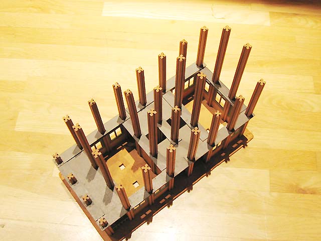 In order for the next layer of wall panels to be level, there must be two layers of plates where wall panels are added on top. Step 6 - Second story wall panels  Diagram III also shows which wall panels to insert where. Again, the lower number is the one to install first, in many cases Part 23. 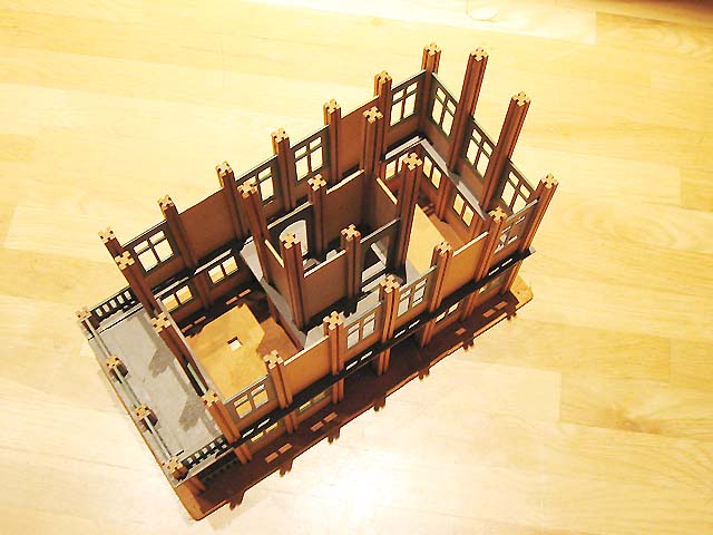 Steps 7 and 8 - Second story top plates/floor plates (two layers) 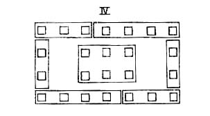 Diagrams IV and V show how to install the two layers of top plates/floor plates. The model is now really sturdy. 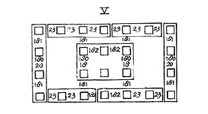 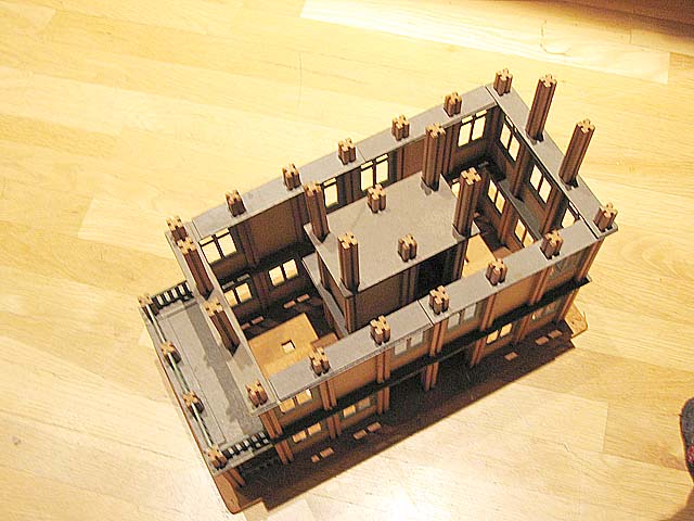 Step 9 - Third floor wall panels  Diagram V also shows which wall panels to install. Step 10 - Roof rafters  Diagram VI indicates which roof rafters to use. Unfortunately, some parts were missing in my set, so my model does not have the side dormer...  Step 11 - Install Roof  There is no diagram for the roof panels. You have to look at the perspective drawing. The roof panels have "teeth" at the ridge so they can interlock. The roof panels are not attached, but kept in place by gravity. 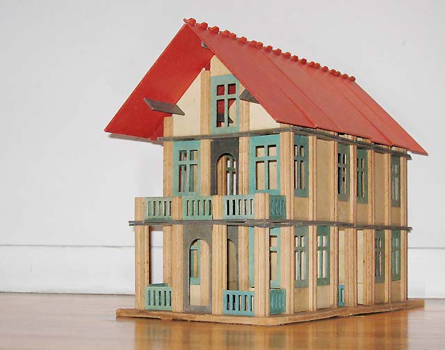 The finished house stands over a foot tall. Notice that the upper openings in the windows are square, while the drawing shows arches. For a while, Mobaco shipped old manuals with the new windows. Later, they fixed some of the manuals. The square openings look more "modern". Interestingly, the doors are still arched! Step 12 - Dismantling All good things come to an end... But taking the model apart is really easy! It only takes a couple of minutes. Try that with a Meccano, Erector or even with a Lego model of this size! Once you build a few models from the instructions and get the hang of it, it's fun to design your own! Or you can try your hand at a Set 5 model:  |
|||||
Thanks to Koos Welling, you can now virtually build any Mobaco model on your computer, using LeoCAD. The only limit is your imagination! LeoCAD is available for Mac and PC. It is open source software that was originally developed to build with Lego. It's really easy to use: you pick a part from a library, and place it where you want it. By dragging one of three arrows you can move a part along any axis. Likewise, parts can be rotated along any of the axes. Once completed, LeoCAD can create a bill of materials of the model, listing how many copies you need of the various parts. You can organize parts into groups and "step' through the construction sequence of a building, allowing you to make animated GIF's such as the one below. LeoCAD is a great way to prototype a design before actually building it with real parts. In addition to Mobaco, Koos is developing libraries for various other vintage toys. Please visit Koos' site for download information, the latest libraries, and detailed instructions. 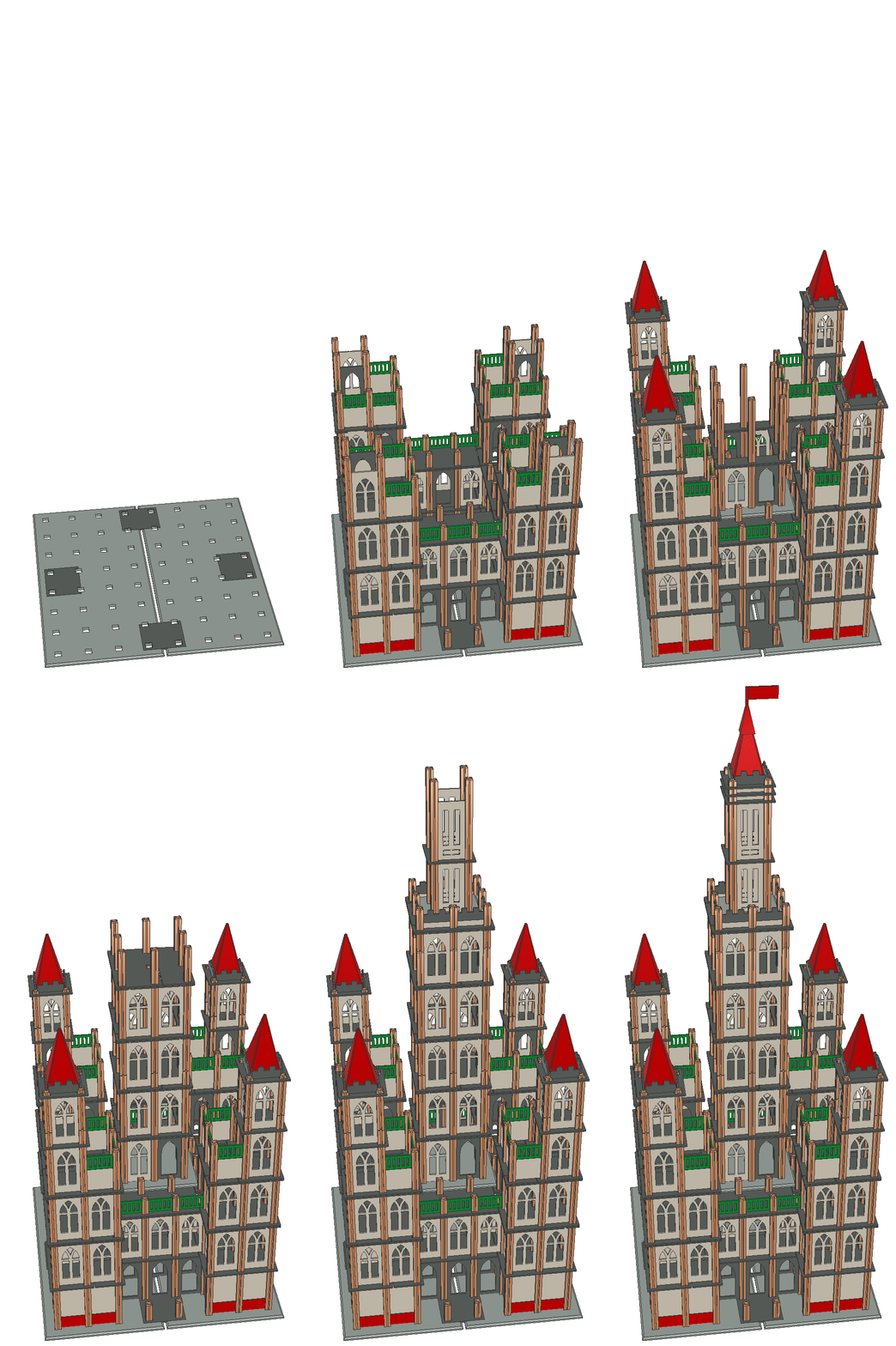 |
||||||
Here a smattering of Mobaco models
built by various (adult) Mobaco builders.
|
||||||
Jump directly to: - Sagrada Familia by Giliam de Valk - Model 75 by Nick Cranendonk - Train Station No. 1, Model 18, Model 33 and Train Station No. 2 by Nick Cranendonk - Whimsical street scene by anonymous - Canal houses by Giliam de Valk - Canal houses, boats and car by Gerard Poort - Model 5-C by Barend Westerveld, Gerard Poort and the Brighton Toy Museum - Dinosaur Museum by Adam Bollod - Doll House by Gerard Poort - Windmill and Small Garages by Ida Gerrits - Tall building in 1931 advertisement by Gerard Poort - The Tower Model by Gerard Poort - Jachthuis St. Hubertus by Gerard Poort - Model 24 by Max Horncy - Buddhist Temple by Giliam de Valk - Models 68, 69 and 77 by Robj Schiff - Jumbo Model E4, Cathedral by Johan Jager - Model 64 with freestyle clock tower by Gerard Poort - Model 77 by Barend Westerveld - Model 79 by Barend Westerveld - Moubal factory in 1919 by Caspar Mol This massive 1:100 scale Mobaco model of the Sagrada Familia was made by by Giliam de Valk in The Netherlands. Where necessary, Giliam made his own columns from standard 12 x 12 mm wood dowels and cut the grooves with a table saw. He also made custom cardboard parts with museum board, such as in the steeple or the tall spires, all in keeping with the spirit of Mobaco. Needless to say, a lot of planning goes into the making of such a model! 
  The Sagrada Familia under construction, with the custom spires before being painted to match the Mobaco roofs:  Sagrada Familia under construction, interior view:  All photographs courtesy of Giliam de Valk This lovely building by Nick Cranendonk is model no. 75 from Set 4, as shown in the Gnomes Manual:  Photo courtesy of Nick Cranendonk Also by Nick Cranendock are these buildings made with pre-1931 parts, which had muted colors and featured round windows. Clockwise from bottom left: Train Station 1 (platform roof and next to it the associated station house), Set 1 building #18, Set 2 building #33, Train Station 2 (station house and in the foreground the associated platform roof). 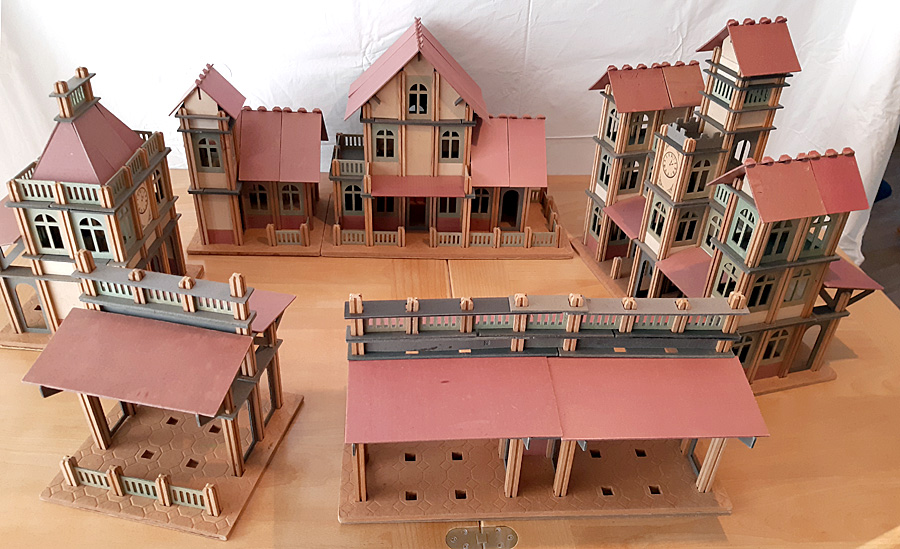 Photo courtesy of Nick Cranendonk Two lady builders turned building with Mobaco into an art form. They created these street scenes with lots of detail, using JoHillCo and Britains hollowcast figures. They say there were also inspired by Frank Lloyd Wright, as can be seen with the leaded glass detail in the third picture. They made a YouTube video of their creation which is fun to peruse! More Mobaco video's on their channel Touareg2. 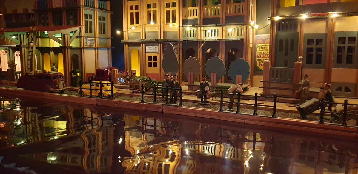 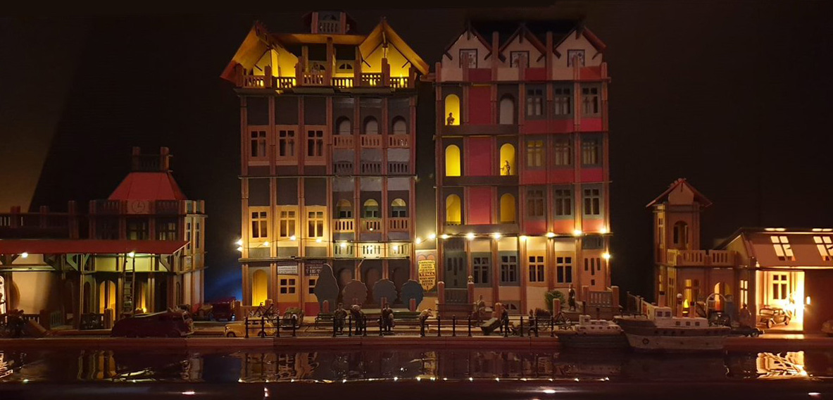  Here a whimsical Giliam de Valk model of homes along an Amsterdam Canal. The gables are obviously home-made parts:  Photo courtesy of Giliam de Valk This inspired builder Gerard Poort to make his own interpretation of an Amsterdam Canal:  Including some creative use of Mobaco to make boats and a car:   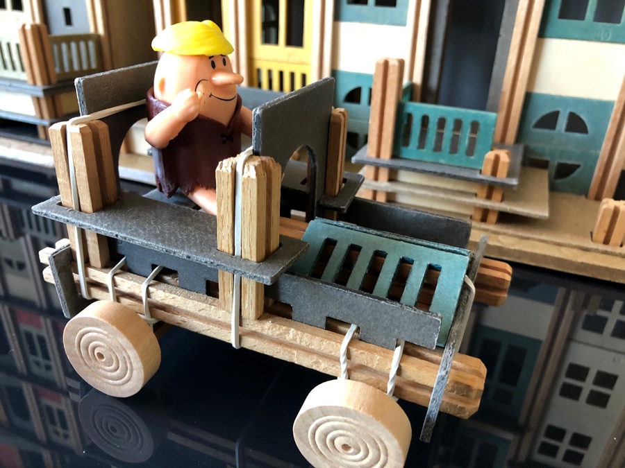 Photo's courtesy of Gerard Poort Barend Westerveld and Gerard Poort built this model from the mythical Set 5, as shown in the Gnomes manual (last page). It requires no less than 4 base plates! Since the manual only shows a perspective of the front, the back of the model is anyone's guess. This model was also recreated by the Brighton Toy Museum for their 25th anniversary. Each builder has their own interpretation of the drawing. Since this is the third model shown in the manual for Set 5, we refer to it as Model 5-C: 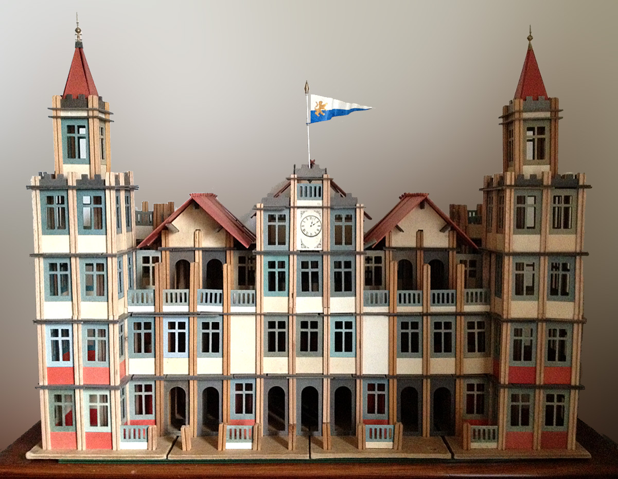  Photo courtesy Gerard Poort Photo courtesy of Barend Westerveld 
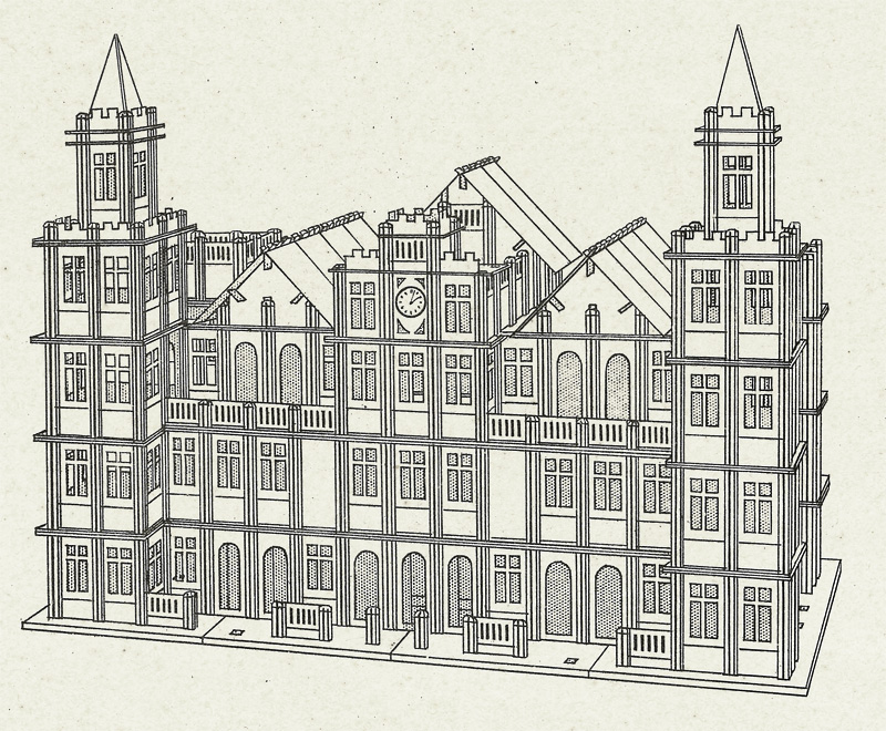 Photo courtesy of Brighton Toy Museum Drawing in Gnomes Manual (last page) Seven year old Adam Bollod was inspired by his grandfather to build this Dinosaur Museum! 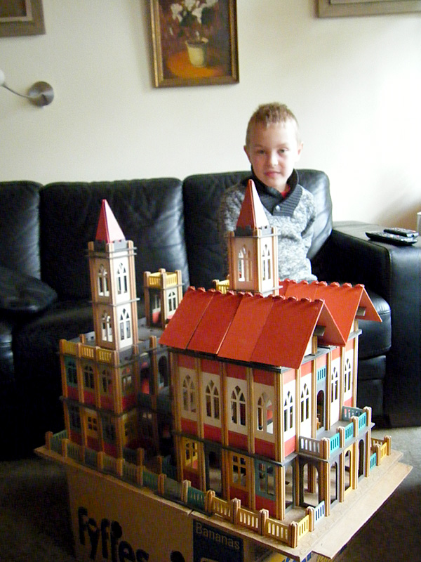
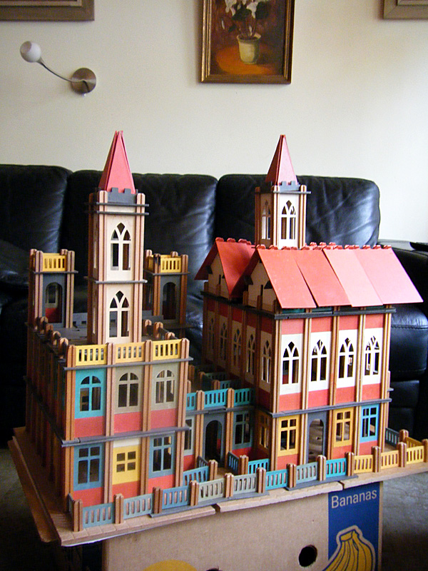 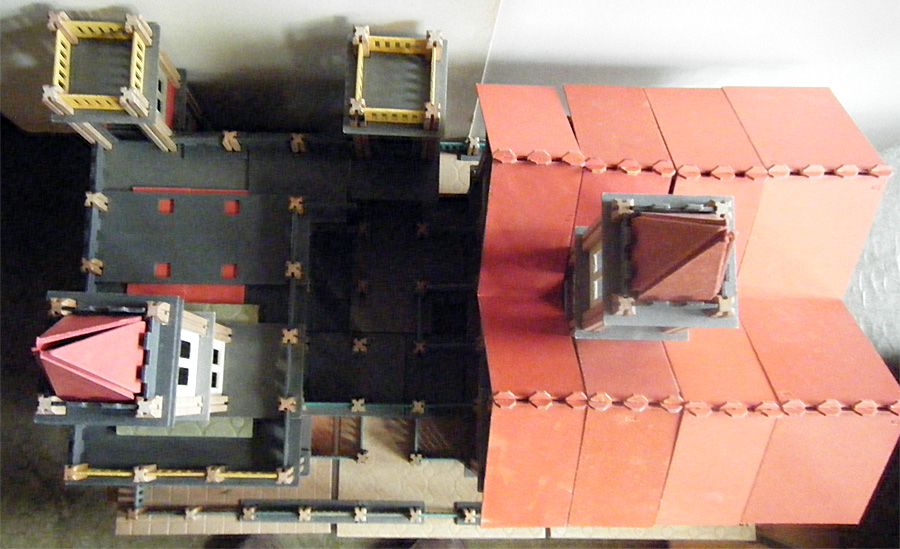 Photo's courtesy of Robj Schiff Gerard Poort built this doll house, complete with LED lighting: 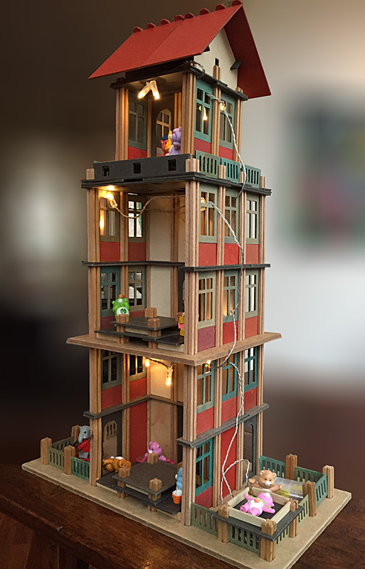 Photo courtesy of Gerard Poort To hide the fact that the upper base plate of the windmill was cut on two sides by a previous owner, Ida put two Small Garages on the sides of this Windmill no. 2, to nice effect: 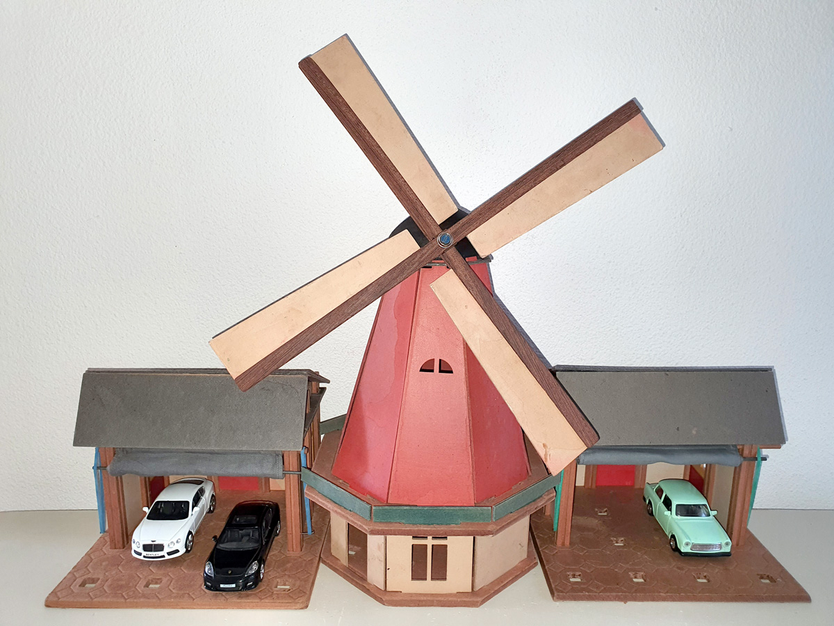 Photo courtesy of Ida Gerrits Several advertisements in the early 1930's featured this undocumented model. Gerard Poort rebuilt it from that one view. He didn't have enough Gothic windows and white solid panels, so he had to improvise a bit! Note: the ad features window panels with narrow tall windows that never existed! Also, it shows an 8 x 8 hole ground plate which didn't exist either. 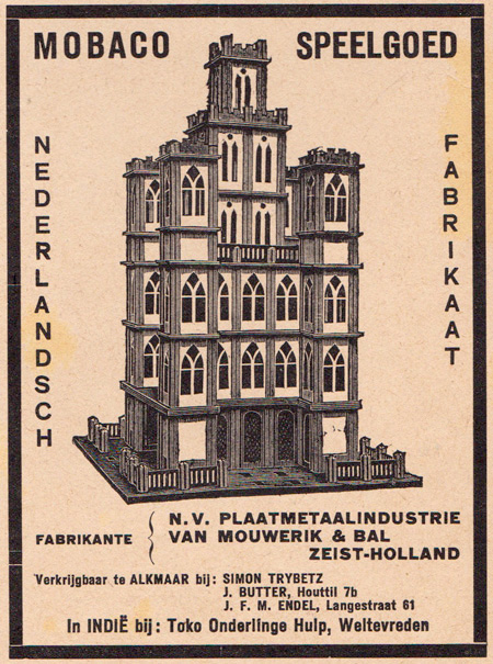  Advertisement courtesy of Leen Kalden. Photo courtesy of Gerard Poort Gerard Poort also built this undocumented model from the cover of the very first Mobaco manual. We refer to this as The Tower Model: 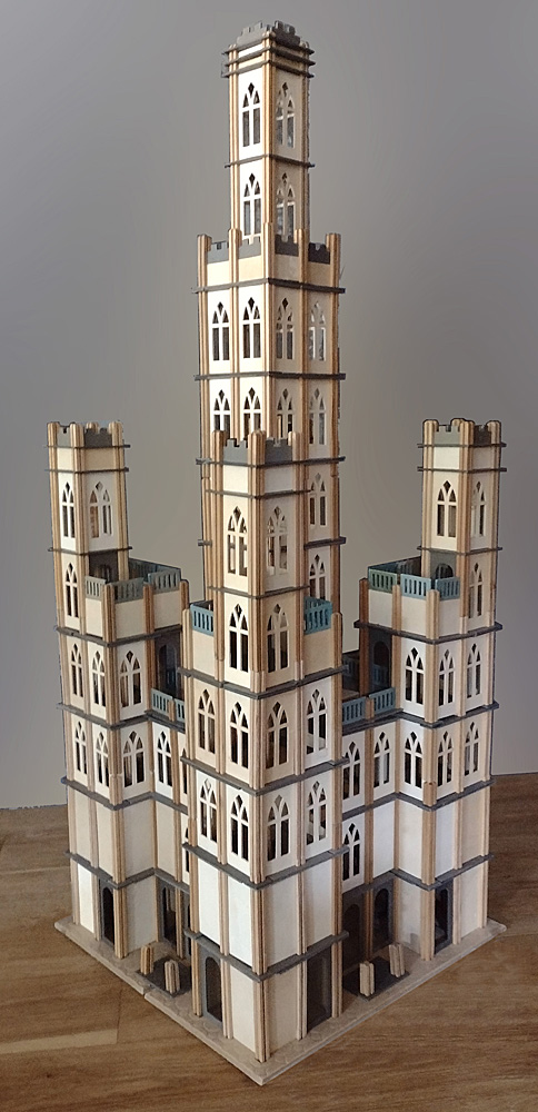
 Photo: CM Angled buildings are impossible in Mobaco. Gerard Poort found a way to build Jachthuis St. Hubertus, designed in 1914 by famous Dutch architect H.P. Berlage for Mr. and Mrs. Kröller-Muller, by angling the ground plates:   Photo courtesy of Gerard Poort. Floor Plan Creative Commons |
||||||
Max
Horncy from New Zealand built this Model
#24 with a pre-1931 Set 1 (round windows and muted roof
panels and windows): Photo courtesy of Max Horncy Buddhist Temple by Giliam de Valk, The Netherlands: 
  Photgraphs courtesy of Giliam de Valk Mobaco models 69 (Swimming Pool, left), 68 (tower) and 77 built by Robj Schiff, The Netherlands:  Photo courtesy of Robj Schiff Jumbo model E4, Cathedral, built by Johan Jager, The Netherlands:  Photo courtesy of Johan Jager |
||||||
Freestyle building by Gerard Poort, very similar to Model 64 but with a clock tower. This model can be seen in the 1926 Mobaco film:  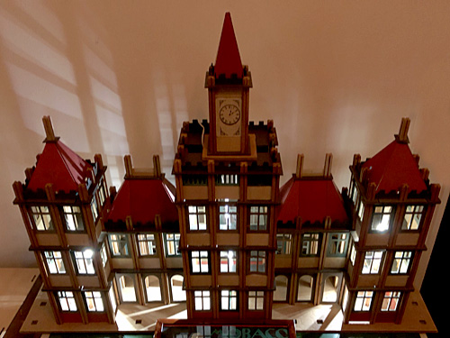 Photographs courtesy of Gerard Poort Model 77 by Barend Westerveld:  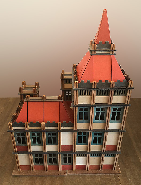 
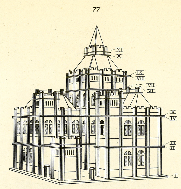 Photographs courtesy of Barend Westerveld Drawing in Gnomes Manual Model 79 by Barend Westerveld: 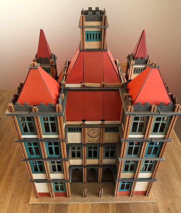
 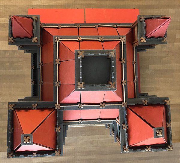
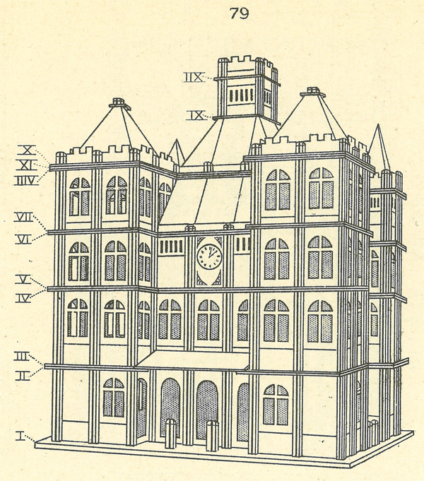 Photographs courtesy of Barend Westerveld Drawing in Gnomes Manual For the Mobaco 1924-2024 exhibition in Zeist, I created a Mobaco version of the original Moubal factory in Zeist in 1919 using LeoCAD. The model was built bij Gerard Poort. 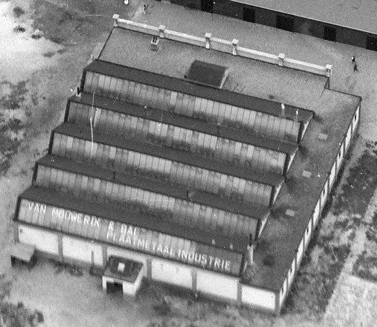 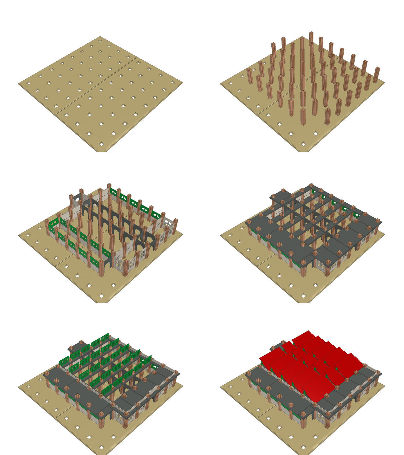 Image courtesy Nederlands Instituut voor Militaire Historie, Beeldbank 2011-2002 LeoCAD renderings: 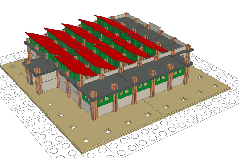  Model in display case at the 1924-2024 100-years Mobaco exhibition in Zeist in spring 2024:  Photo courtesy of CM Model in display case at the Mobaco exhibition at Speelgoedmuseum "Op Stelten" in Oosterhout in summer 2024:  Photo courtesy of CM |
||||||
Mobaco at 1/3rd scale for train
layouts
|
||||||
| In 1926, Moubal brought out its first two
special sets: Station No. 1 and No. 2. They went
well with 1 gauge trains. They were made using
standard Mobaco parts. Here Strain Station No. 2. Left the main building, right a platform with canopy and sales window: 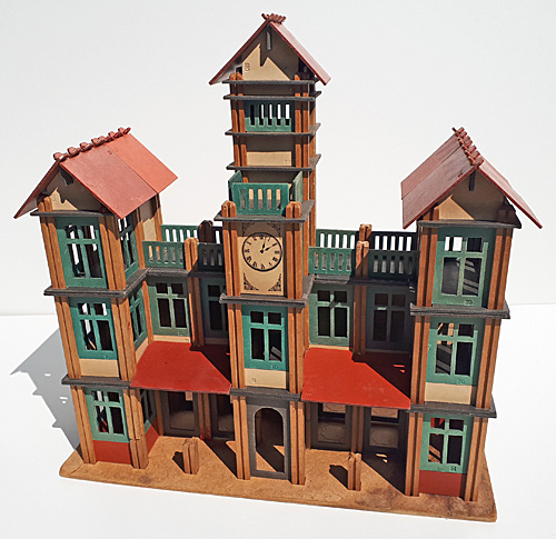 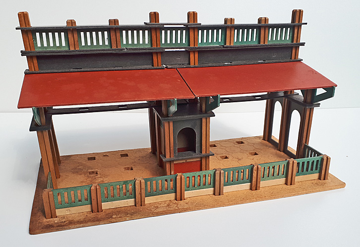 Mobaco model and photographs courtesy of Koos Welling After a conversation with a train friend with an impressive layout at H0 scale, I thought it would be great to make a mini version of the Mobaco train station, scaled to H0. After some measuring I decided that making Mobaco at 1/3rd scale would be about right. That meant that columns would have a section of 4.2 x 4.2 mm with grooves 1 mm wide and 0.8 mm deep, and wall panels would be 16.7 x 34.0 mm x 0,83 mm thick. Minuscule but doable. Next was figuring out how! Friend Koos Welling has a CO2 laser cutter and a CAD library of Mobaco parts, so making parts seemed a no-brainer. However, finding cardboard of the right thickness posed a challenge. Finally we settled on URSUS 300 g/m2 paper which is appr. 0.37 mm thick. Two layers would be a tad shy of the required 0,83 mm thickness, but close enough. The sheets are 50 x 70 cm, and when cut in half they fit the laser cutter well. The paper is available in 52 colors, we settled on these 4:  I experimented with three types of glue: white paper glue, spray paint glue, and ironing a layer of plastic between two layers of paper (a YouTube suggestion). The latter worked surprisingly well, except that my iron wasn't quite hot enough to create a solid bond. White paper glue resulted in slight bending of the cardboard, plus it took long to dry. I'm no big fan of spray cans in general, but spray paint glue worked fast and good. However, too much glue results in permanent stains, so be judicious with how much you apply. Dry it below some books to keep it flat. Koos did some laser tests to figure out the correct settings. At 15% power and 75 mm/sec, the laser only etches the paper (see bottom left of test sheet). At 30% power and 20 mm/sec, it burns a pretty wide cut (top right). For expediency, faster is better so 75 mm/sec at 25% would seem ideal. However, at that speed curves don't come out nice, so we settled on 40 mm/sec at 25W. 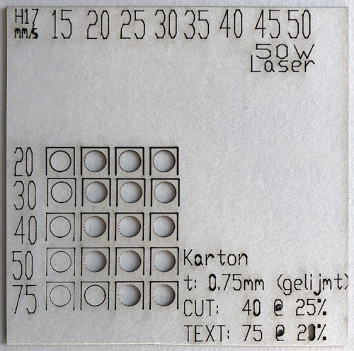  Laser test with various intensities (left to Laser cutter at work. The yellow window filters out harmful rays right) and various speeds (top to bottom). In the machine, the cardboard rests on metal reglets spaced appr. 5 cm (2" inches) apart. If you cut out an entire part, it falls between the reglets to the bottom of the bed. But it doesn't fall straight down, so when the laser is cutting an adjacent part, it may cut off a corner of a finished part resting below.  CO2 laser cutter
at work. The laser beam itself is invisible (wear
goggles with laser filters!), but the
burning paper is quite obvious. It goes fairly fast, still, an entire sheet of parts will take half an hour. So we adapted the parts such that a small tab kept them attached to the sheet. After lasering, you separate the parts with an Exacto knife. With small parts, the tab can be so small that you could just tear it off, but for perfectionists, cutting is better! Here the result of the laser cutting:  Cutting the tabs was still quite arduous. It helps that many of the parts line up, so with a metal ruler you can cut a row at the time. Your hands get quite sooty from all the burnt edges! The base plates were made from masonite, and the laser cutter took its sweet time to cut all the holes. But the result is nice, and I find the black sides (burnt wood) aesthetically quite pleasing. 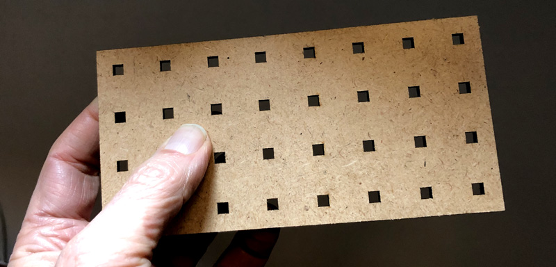 Next was making posts. At 4.2 x 4.2 mm (appr. 3/16") they posed a challenge! Experiments with a regular table saw went nowhere, it's simply too big and powerful, and the posts disappear in the gap next to the saw. Then I discovered the Proxxon Micromot tools, specially made for model building! I was able to borrow a Proxxon KS 230 table saw. It's adorably cute! But it only has an 85 W motor, and at first I had a hard time cutting the wood. It turned out the saw blade was dull and at 58 mm diameter (~2-1/4"), a tad large for the motor. 
 For making the grooves, I ordered a wider 1.1 mm saw, which also has a smaller diameter (50 mm, appr 2", part no. 28 017) and that made all the difference in the world. To match the color and feel of the real posts, I cut up original Mobaco columns. Out of each post you can get 4 mini posts. So out of every Mobaco post you get approximately 12 mini posts to scale. The aluminum guide that comes with the Proxxon looks a bit flimsy but actually works well. 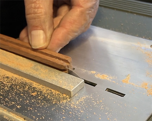
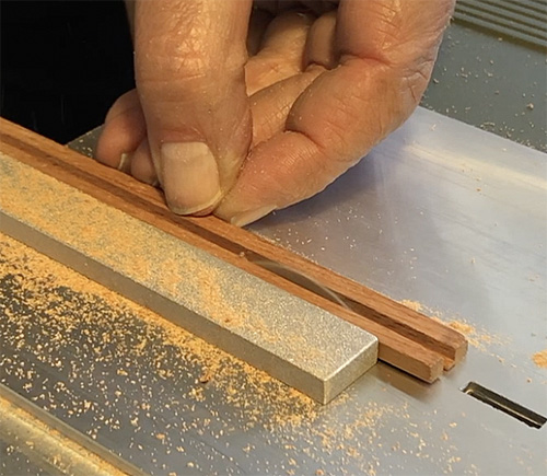 Cutting down Mobaco posts. The saw is
too small to cut through the post, so it requires
8 cuts to create 4 posts. Really watch that blade, as your fingers get awfully close!  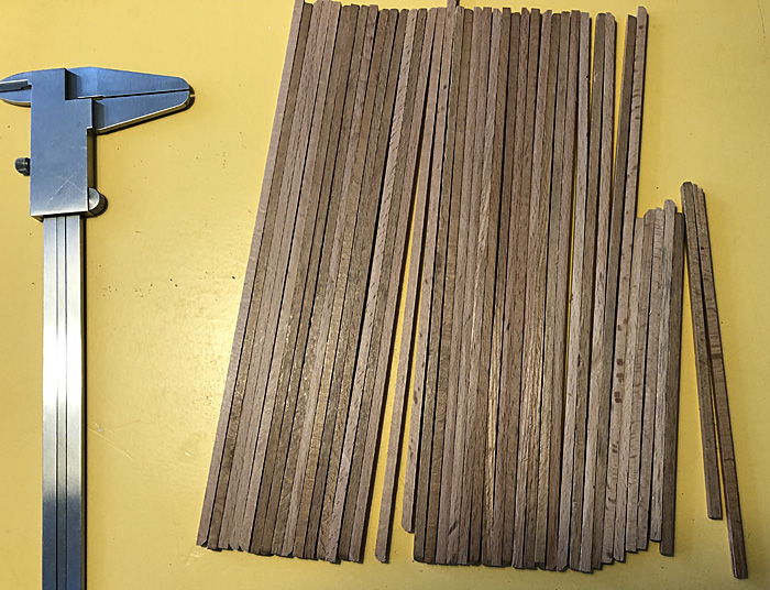 The cut posts. Notice the color
difference between fresh cut sides and aged sides.
The Proxxon doesn't have a height adjustment for the saw blade, so I made a jig for cutting the grooves. Getting it right was a bit finicky, but once done, cutting the grooves went smoothly. At first the grooves were 0.1 mm too deep which was fixed by putting a piece of paper below the jig. 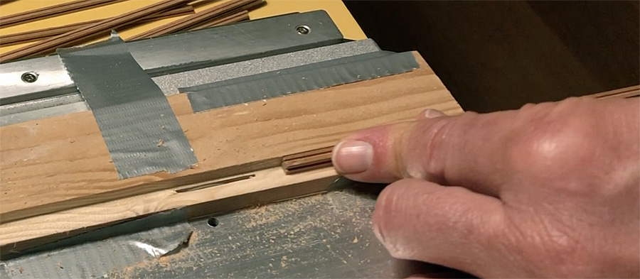 Then it was time to cut the posts to length. Since the base plate is 1 mm too thick and I still needed to sand the ends, I made them 2 mm too long. To get straight cuts with the table saw, I taped the posts together. 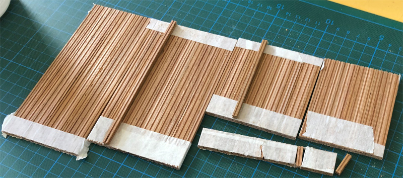 Last step was to sand a taper to the top op the posts and clean up the bottom. It turned out that the best way to do this was by hand. Like the entire endeavor, this required patience and perseverance!  Then it was time to build! It's all rather small, but it's possible to build the model without using tweezers. For another friend, Koos and I also made an H0 version of the "Palace" shown on the cover of the very first Mobaco manual and in some later advertisements. Below the result. You can't really tell it's smaller than the original without scale references, a sign that it's a good scale model!  TRAIN STATION NO. 2  The clock face was laser printed in mirror image, and transferred to a white panel using thinner. It required several tries to get it right.   BUILDING THE PALACE Before we built it, Koos virtually assembled the palace in LeoCAD. The palace actually consists of three buildings that are stacked. This gave us a bill of materials for making the parts.  Design and virtual model courtesy of Koos Welling I then grouped the parts into 20 layers, which became the construction manual:  When lifting the completed upper stages for stacking, the poles shouldn't fall through the base plates. So I glued a sheet under the base plates with 3M transfer tape:   Ready to go! 627 parts (and some extra):  It took 3 hours to put it together (after 60 hours of preparation). Here the result: 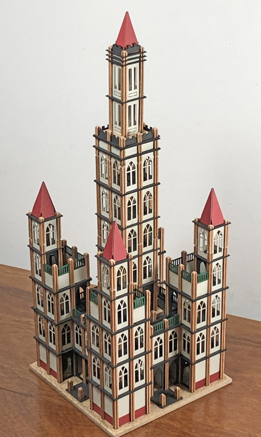
  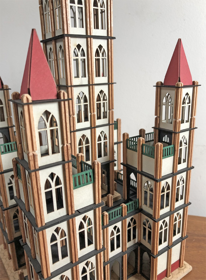   It's adorable! 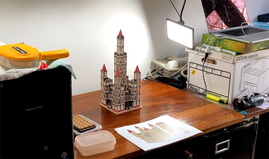 |
||||||
|
|
||||||
| In 2024, Mobaco
exists 100 years! A group of Mobaco enthusiasts
thought the centennial would be a nice occasion for an
exhibition in a Dutch museum. We approached the
National Railway Museum in Utrecht, the city where van
Mouwerik & Bal originally started. To woo the museum, we built a Mobaco replica of the Maliebaan train station, where the museum is housed. In the end, the museum declined, but it's still a nice model! Below what the building looks like. It opened in 1874. The round windows and doors lend themselves well for a Mobaco model.  Aerial 1927. In the early 1960's, the arched roof over the platforms was replaced with a flat roof:  Image courtesy of Het Utrechts Archief Around 1900: 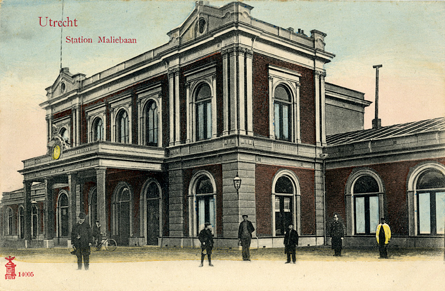 Image courtesy of Het Utrechts Archief First step was to create a virtual model with Koos Wellings' newly released LeoCAD library. It took me five attempts before I felt the proportions were about right and the various cornices were correctly modeled. Since the roofs have a low slope, I decided they should be custom made, as well as the little gables on the front and sides.  By tracing photographs in CAD, I measured the roof angles as best possible... 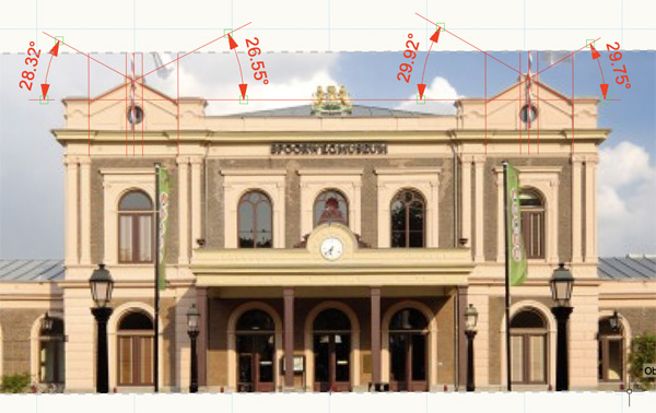
 ... and drew up a roof template for the builder:  Barend Westerveld then built the model, and embellished it with an antique train, car and figurines. I think it came out great! Under construction: 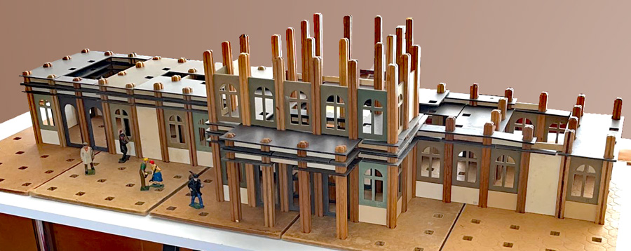 The Mobaco Maliebaanstation completed:  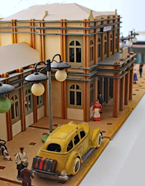
 All aboard!  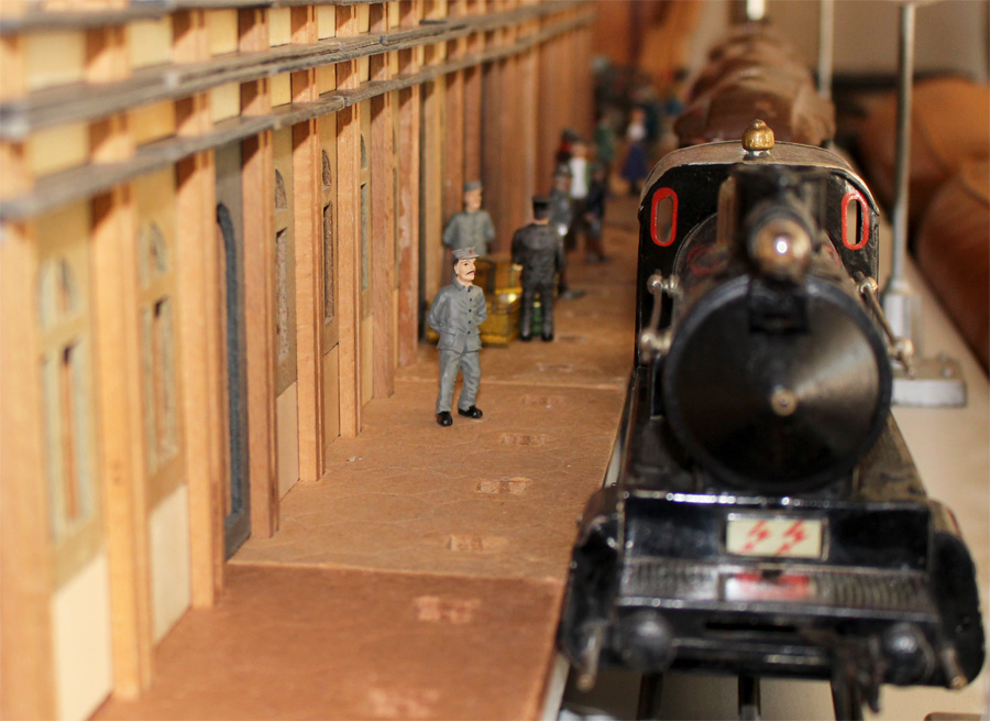 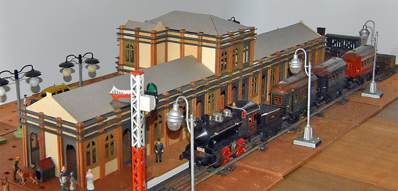 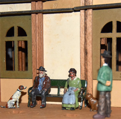
 |
||||||